How to Understand the Role of Insulation in Pipe Supports?

Time:2026-09-08 Author:Liam
0%

Understanding pipe supports requires more than examining steel brackets, clamps, or welded shoes. Insulation changes how those components perform in real operating conditions. The key question is: what is the role of insulation in pipe supports? It helps control heat transfer, prevent condensation, and protect nearby structures from extreme temperatures. It can also reduce energy loss along chilled or heated pipelines. However, insulation is not simply a soft layer placed around the pipe. Its thickness, density, moisture resistance, and compression strength must suit the support arrangement.

Small details matter. At a support point, a rigid insulation insert may carry the pipe load while preserving the thermal barrier. Without that insert, insulation can flatten under pressure. A cold pipe may then develop a damp ring, corrosion, or unwanted heat gain. Hot piping creates different concerns, including heat damage to support materials and unsafe surface temperatures. Experienced engineers usually review operating temperature, pipe weight, movement, vibration, and maintenance access together. Relevant project specifications and recognized engineering standards should guide the final selection.

The answer is not always neat. A support design that appears efficient may create a thermal bridge. A thicker insulation layer may also require a longer clamp or wider support shoe. Field inspections often reveal gaps that drawings do not show. This article explains the practical relationship between insulation and pipe supports, while recognizing that each system needs careful verification. Good performance depends on coordinated design, suitable materials, and workmanship that survives actual plant conditions.
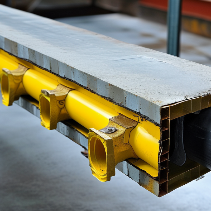
How to Understand the Role of Insulation in Pipe Supports?

Classify Pipe-Support Insulation by Temperature, Material, and Service

Insulation in a pipe support does more than reduce heat loss. It protects the pipe, controls surface temperature, and limits corrosion under insulation. In field inspections, I treat the support area as a thermal bridge. A bare clamp can create a cold stripe. Small detail. Yet it may distort temperature readings and damage the insulation jacket.

Temperature provides the first useful classification. Cryogenic lines require insulation that stays flexible and resists moisture intrusion. Hot lines need materials that tolerate continuous heat without excessive compression. Moderate-temperature services may use lighter systems, but the support must still carry the pipe load. A crushed insert creates a gap, and heat soon finds it. Design values should come from tested compressive strength, not appearance alone.

Material choice depends on service conditions. Closed-cell insulation helps resist water, while mineral-based systems may suit higher fire or temperature demands. Vapor barriers are essential on cold lines. Chemical exposure, outdoor weather, vibration, and maintenance access also influence the selection. For example, a coastal support may need sealed joints and corrosion-resistant hardware. Process lines carrying clean fluids require careful surface control during installation. I have seen good insulation fail because installers cut it too tightly around a clamp. That shortcut is tempting, but it blocks movement and weakens the jacket. Measure twice. Pipe-support insulation works best when thermal performance, mechanical loading, and service conditions are reviewed together.

Quantify Heat Loss Using Insulation Near 0.04 W/m·K Conductivity

Insulation around pipe supports does more than improve appearance. It controls heat flow, limits condensation, and protects the support from extreme temperatures. For a practical estimate, use insulation with thermal conductivity near 0.04 W/m·K. Lower conductivity usually means less heat loss, but installation quality remains critical.

For a pipe with a 50 mm outside radius, 100 mm insulation thickness, and a 100°C temperature difference, the cylindrical equation gives approximately 36 W of heat loss per metre. The calculation is Q = 2πkLΔT / ln(r2/r1). Here, k is 0.04 W/m·K. A ten-metre section would therefore lose about 360 W under ideal conditions. Real results can be higher. Small gaps matter.

Supports interrupt the insulation layer and create thermal bridges. Metal clamps can carry heat directly from the pipe to the structure. A properly fitted insulation insert should cover the support area without excessive compression. Sealed joints also reduce air movement and moisture entry. Field inspections often reveal thin spots behind clamps, where heat loss becomes difficult to see but easy to measure with infrared equipment.

This estimate assumes dry insulation and stable temperatures. Actual conductivity may change with moisture, aging, or compression. That estimate is imperfect. Engineers should verify material data at the expected mean temperature and check support loads separately. Even a small correction for damaged jacketing can change the final result.

Assess Support Loads Under ASME B31.1 and MSS SP-58 Requirements

How to Understand the Role of Insulation in Pipe Supports?

Insulation changes more than the pipe’s outer temperature. It adds weight, increases diameter, and can alter support contact. A realistic load assessment includes the pipe, contents, insulation, jacketing, valves, flanges, and temporary test water. Small details matter.

Under ASME B31.1, support design should address sustained, thermal, and occasional load cases. The empty operating load may differ sharply from the hydrostatic test load. Thermal expansion can also shift reactions between supports. A rigid support may carry more load than expected after the pipe heats. It can also restrict movement and create unwanted stress. Do not treat every support reaction as constant.

MSS SP-58 helps guide the selection and application of pipe hangers and supports. Insulated lines often need shields, saddles, or protection against insulation crushing. The shield must spread the load without creating a thermal bridge or damaging the jacket. Field measurements should confirm actual insulation thickness and support alignment. Drawings are not always perfect. A practical review should check gaps, weld locations, spring settings, and nearby structures. One common mistake is calculating insulation weight but ignoring water trapped inside the jacket. That assumption deserves another look. Reliable support assessment combines code-based load cases, site evidence, and clear engineering judgment.

Prevent Thermal Bridges with 25–50 mm Insulation Continuity

How to Understand the Role of Insulation in Pipe Supports?

Pipe supports carry loads, control movement, and help maintain insulation continuity. A metal support can create a direct thermal bridge through the insulation layer. Heat then escapes from warm pipes, or enters chilled pipes, causing energy loss and surface condensation.

Maintain 25–50 mm of continuous insulation around the support transition. The exact thickness depends on pipe temperature, humidity, insulation material, and local design requirements. Use a load-bearing insulation section where the pipe rests, then seal its joints carefully. Even a narrow gap can expose cold metal and weaken the entire detail. Field inspections often find compression, torn jackets, or displaced insulation after installation. These small defects matter.

Tips: Check the support detail before insulation work begins. Keep vapor barriers continuous on cold-service pipes. Avoid crushing soft insulation beneath heavy pipework. Confirm clearances for expansion and movement. Photograph concealed areas before closing them. A qualified engineer should verify loads, temperatures, and condensation risk. The practical compromise is not always perfect, and crowded pipe racks can make the 25–50 mm target difficult. Review the detail early, not after the pipe is fixed.

Verify Moisture Control, CUI Risk, and Support Integrity During Inspection

How to Understand the Role of Insulation in Pipe Supports?

Insulation protects process temperature, personnel, and pipe supports. It can also hide trapped water. That is the difficult contradiction. During field inspections, I look for wet insulation, damaged jacketing, open seams, and rust stains below support clamps. These details often appear before serious corrosion becomes visible. The NACE IMPACT study estimated global corrosion costs at about 3.4% of global gross domestic product. Corrosion under insulation remains a recurring concern because moisture can stay trapped against steel for long periods. Sometimes, the insulation looks dry outside. The support is not.

Moisture control must be checked around shoes, saddles, clips, and penetration points. Inspectors should verify sealed weather barriers and confirm that drainage paths remain open. CUI risk increases when insulation is compressed, poorly fitted, or repeatedly disturbed. Support integrity also requires attention. Look for distorted steel, thinning at contact points, loose fasteners, and unexpected pipe movement. API RP 583 identifies insulation systems, moisture, temperature, and inspection access as important CUI considerations. Yet visual inspection alone can mislead. I have seen clean-looking jackets covering heavily degraded support steel. That possibility deserves more attention.

Tips: Photograph every damaged seam before opening insulation. Record surface temperature and recent weather conditions. Use targeted insulation removal, thickness measurement, and non-destructive testing where risk is higher. Check low points first. Keep records tied to each support location. Perfect inspection plans rarely survive field conditions. Review them after every finding.

FAQS

: How should pipe-support insulation be classified?

: Classify it by temperature, material, and service conditions. Cold lines need flexible insulation and strong moisture resistance. Hot lines need stable performance under continuous heat. Moderate services may use lighter systems. The support still carries the load.

Why is the support area a thermal bridge?

Bare clamps can create cold stripes across the insulation. These stripes may distort surface-temperature readings. They can also damage the outer jacket. Small gaps matter.

Which insulation materials suit different services?

Closed-cell materials help resist water entry. Mineral-based systems may suit higher temperature or fire demands. Cold lines also need reliable vapor barriers. Chemical exposure, weather, vibration, and access affect selection.

What loads should engineers include?

Include the pipe, contents, insulation, jacket, valves, and flanges. Include temporary test water when relevant. Operating loads may differ greatly from test loads. Do not assume every support reaction stays constant.

How can insulation prevent support damage?

Use shields, saddles, or load-spreading inserts where needed. These parts should prevent crushing without creating a strong thermal bridge. Check actual insulation thickness and support alignment. Drawings can be wrong.

What installation mistakes commonly reduce performance?

Cutting insulation too tightly around a clamp is a common mistake. It can block movement and weaken the jacket. A crushed insert creates a gap. Heat soon finds it.

How should inspectors check moisture and corrosion risk?

Look for wet insulation, open seams, damaged jackets, and rust stains. Check around shoes, saddles, clips, and penetration points. Confirm weather barriers are sealed. Keep drainage paths open. The outside may look dry.

Which field details deserve special attention?

Inspect low points first. Record support locations, surface temperatures, and recent weather. Photograph damaged seams before opening insulation. Check loose fasteners, distorted steel, thinning contact areas, and unusual movement. Visual inspection alone can mislead.

Conclusion

Understanding what is the role of insulation in pipe supports requires looking beyond temperature control. Pipe-support insulation should be classified according to operating temperature, insulation material, and service conditions, because each combination affects thermal performance, mechanical behavior, and durability. Insulation with conductivity near 0.04 W/m·K can help quantify and reduce heat loss, while proper thickness and continuity limit energy transfer at support locations. Designers must also assess support loads, expansion effects, and material strength in accordance with ASME B31.1 and MSS SP-58 requirements.

A reliable design should maintain approximately 25–50 mm of insulation continuity around supports to prevent thermal bridges and uneven temperature distribution. Moisture control is equally important, particularly where condensation or water ingress could increase corrosion-under-insulation risk. During inspection, personnel should verify insulation condition, vapor sealing, drainage, support alignment, and evidence of corrosion or deformation. This integrated approach helps preserve pipe integrity, improve energy efficiency, and ensure that supports remain dependable throughout the system’s service life.

Liam

Liam

Liam is a dedicated marketing professional with a profound expertise in the industry, where he excels at highlighting the unique advantages of our core products. With a keen understanding of market trends and consumer needs, Liam frequently updates our company’s professional blog, providing......