Determining what standards apply to pipe supports is a design decision, not a paperwork exercise. A support may carry weight, control thermal movement, limit vibration, or resist occasional loads. Each function can change the governing requirements. The answer also depends on the piping system, fluid, temperature, pressure, location, and project specification.
ASME B31.3, Process Piping, provides design requirements for many chemical, petroleum, pharmaceutical, and process facilities. ASME B31.1 addresses power piping, including systems connected to boilers and power-generation equipment. For support materials, fabrication, inspection, and testing, MSS SP-58 remains a widely used technical reference. Its guidance covers hangers, supports, materials, and installation practices. Engineers may also consult MSS SP-69 for selection and application guidance. These documents do not replace engineering judgment. They work together.
Field experience shows why this matters. A support placed beside a hot elbow can restrict thermal movement. A poorly aligned rod hanger can bend after commissioning. API 570 inspection guidance emphasizes evaluating piping condition and support-related deterioration during in-service inspection. The Energy Institute’s Process Safety Fundamentals also stresses disciplined design and maintenance controls. These professional publications support a practical question: what standards apply to pipe supports in this specific service? Project specifications, local regulations, owner standards, seismic criteria, and fireproofing requirements may add another layer. Sometimes, the governing document is not obvious. That uncertainty deserves review, not guesswork. A careful standard matrix, checked by a qualified piping engineer, can connect each support detail to a defensible technical requirement. Mistakes still happen. The important point is recognizing them early and correcting the design before loading, vibration, or thermal movement exposes the weakness.
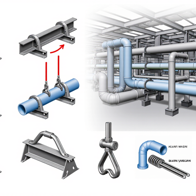
Pipe supports follow the piping system’s governing code. ASME B31.1 normally covers power piping, including boiler external piping and utility steam systems. ASME B31.3 applies to process piping in chemical, refining, pharmaceutical, and similar facilities. EN 13480 covers metallic industrial piping, often within European regulatory frameworks. The classification should follow service, location, design pressure, temperature, and jurisdiction. It should not follow the contractor’s favorite template.
Industry data supports this caution. The IOGP Safety Performance Indicators report tracks process-safety events across thousands of operating assets. Its findings repeatedly connect loss-of-containment risk with weak mechanical integrity controls. A poorly selected support can create local stress, vibration, or thermal restraint. A neat calculation may still hide a bad assumption.
Tips: Write the code basis on the piping line list. Check whether the system is power, process, or industrial piping. Then verify support loads, friction, thermal movement, seismic demands, and structural connections. ASME B31.1 and B31.3 provide different design frameworks, while EN 13480 requires alignment with European conformity and material practices. Project specifications may add support requirements, but they cannot quietly replace the governing code. In practice, engineers sometimes classify borderline utility lines too quickly. That deserves review. Use the design conditions, not the pipe label.
How to Know What Standards Apply to Pipe Supports?
Match Support Types and Loads with MSS SP-58 and MSS SP-69
Pipe support selection starts with service conditions, not appearance. MSS SP-69 helps engineers select suitable support arrangements for specific piping systems. MSS SP-58 addresses support materials, construction, dimensions, and performance expectations.
A chilled-water line may need guides, anchors, and insulation protection. A steam line may require a spring support for vertical movement. Heavy valves and flanges can create concentrated loads near connections. These details should appear in the support schedule, not remain as field assumptions.
Load paths matter.
During design reviews, compare operating weight, hydrotest weight, insulation weight, and occasional loads. Check whether the structure can accept each reaction. Then confirm support spacing, rod capacity, and attachment details against the applicable requirements of MSS SP-58. Use MSS SP-69 to verify the selected support type fits the movement and service conditions.
Field experience often reveals missed details. A support can meet its rated load yet restrict thermal expansion. A guide can look correctly installed but transfer vibration into nearby equipment. I have also seen insulation omitted around a clamp, creating avoidable condensation and corrosion risk. These mistakes deserve review before fabrication.
The standards guide selection, but project specifications and engineering calculations still control the final decision. Confirm current editions, temperature ranges, corrosion exposure, and installation tolerances. When conditions are uncertain, document the assumption and revisit it.
A pipe support review should begin with the flange connection, not the support steel. ASME B16.5 covers flanges and flanged fittings from NPS 1/2 through NPS 24. Its pressure–temperature tables depend on material group, pressure class, and operating temperature. For a common forged carbon-steel material group, the 2022 tables show a Class 150 rating of about 285 psi at 100°F. At 400°F, that rating falls to about 170 psi. The difference is significant. A flange that looks oversized may still be unsuitable after heating.
Do not treat the class number as a universal pressure value. Check the exact material, facing, gasket, bolts, corrosion allowance, and design temperature. ASME B16.5 provides the rating data, while piping design rules such as ASME B31.3 address system loads and flexibility. Support spacing alone does not prove flange safety. Thermal expansion can create bending moments at the flange. I have seen drawings that passed a visual review but lacked a sustained-load check. That weakness deserves attention.
Tips: Record the flange material group and design temperature beside every support detail. Compare the table rating with internal pressure, hydrotest pressure, and external loads. Confirm bolt stress and gasket seating with the responsible piping engineer. A spreadsheet helps, but it can still hide a wrong temperature assumption. Never rely on memory. Cite the ASME B16.5 edition used.
Pipe support standards become clearer when thermal movement, flexibility, and allowable stress are checked together. A fixed support can restrain expansion and transfer large loads into the pipe wall or nearby equipment. The basic movement estimate is ΔL = αLΔT. For example, a 30-meter carbon-steel line exposed to a 250°C temperature change may expand about 90 millimeters, using an expansion coefficient near 12 × 10⁻⁶/°C. ASME B31.3 material data and temperature provisions should confirm the selected value.
Small gaps matter. Support spacing alone does not prove flexibility. ASME B31J-2023 provides stress-intensification and flexibility-factor methods for bends, tees, and other components. Engineers should check sustained loads, displacement stress range, and occasional loads from wind or seismic actions. A guide may slide longitudinally but resist lateral movement. A line stop may control direction while increasing anchor force. These details often decide whether equipment nozzles remain within their allowable loads.
Allowable stress is not simply yield strength divided by a convenient factor. ASME B31.3 determines limits from material strength, design temperature, and code rules. API 579-1/ASME FFS-1 also emphasizes that defects, thinning, and local stresses can change an assessment. Do not guess. A polished calculation can still hide incorrect friction values, missing insulation weight, or an unrealistic operating cycle. Reviewers should compare the model with field conditions, including shoe clearance, spring travel, and hot alignment. The assumptions may be imperfect, but documenting them makes correction possible.
How to Know What Standards Apply to Pipe Supports?
Document Materials, Fabrication, Testing, and Installation to MSS SP-89
MSS SP-89 provides a practical framework for fabricating and installing pipe supports. It helps teams record what was built, how it was checked, and where it was installed. The project specification and governing design code still control requirements beyond this standard.
Begin with material documentation. Record support type, material grade, thickness, heat number, and applicable certificates. Keep approved drawings beside purchase records. A simple tag on each support can connect the physical item to its inspection file.
Small details matter.
During fabrication, document cutting, forming, welding, and dimensional checks. Record qualified welding procedures and inspector findings when required. Check hole locations, base plates, clamps, and attachment points before shipment. A support can look strong but still fail alignment checks.
Testing should match the project risk. Record visual inspections, weld examinations, coating checks, and load or fit-up verification when specified. Do not invent acceptance criteria after fabrication. Confirm them before work begins.
Installation records should show support identification, location, elevation, orientation, and final condition. Photograph anchor points and nearby welds before insulation hides them. Note field changes, temporary supports, and unresolved items honestly.
Records are often incomplete.
That weakness deserves attention. A missing revision or unclear inspection date can delay approval and complicate future maintenance. Reviewing the documentation with fabricators, inspectors, and installers can expose assumptions before they become costly corrections.
| Project Stage | Applicable Standard or Document | Information to Verify | Typical Evidence or Record |
|---|---|---|---|
| Basis of Design | MSS SP-58 MSS SP-69 | Use MSS SP-58 for pipe-hanger and support materials, design, manufacture, selection, application, and installation principles. Use MSS SP-69 when selecting and applying standard support types for the piping arrangement. | Support design criteria, support schedule, load summary, movement requirements, and approved support details. |
| Fabrication and Installation Practice | MSS SP-89 | Apply MSS SP-89 to fabrication and installation practices for pipe hangers and supports, including workmanship, dimensional control, attachment arrangements, field fit-up, and installation of support components. | Fabrication drawings, dimensional inspection reports, installation checklists, and field verification records. |
| Piping Design Basis | ASME B31.1 ASME B31.3 | Select the piping code required by the service. ASME B31.1 applies to power piping systems; ASME B31.3 applies to process piping systems. Confirm design temperature, pressure, weight, thermal movement, flexibility, and occasional loads before finalizing support locations. | Approved piping design basis, line list, stress analysis, isometric drawings, and support load report. |
| Pipe and Fitting Interface | ASME B16.5 ASME B16.47 | Check flange dimensions, bolt clearances, support clearances, and access requirements. ASME B16.5 covers flanges and flanged fittings in nominal sizes through NPS 24; ASME B16.47 covers large-diameter steel flanges. | Piping arrangement drawings, flange schedules, clearance checks, and installation inspection records. |
| Support Material Selection | MSS SP-58 ASTM A36/A36M ASTM A123/A123M | Specify material grade, thickness, corrosion allowance, temperature suitability, and compatibility with the supported pipe. ASTM A36/A36M may be used where carbon structural steel is specified. ASTM A123/A123M applies to hot-dip galvanized coatings on iron and steel products when galvanizing is required. | Material requisitions, certificates of conformity, material certificates, coating certificates, and traceability records. |
| Bolts, Rods, and Fasteners | ASTM A193/A193M ASTM A194/A194M ASTM F3125/F3125M | Select fastener materials according to design temperature, corrosion exposure, strength, and connection type. ASTM A193/A193M covers alloy- and stainless-steel bolting for elevated-temperature or high-pressure service; ASTM A194/A194M covers nuts for similar service; ASTM F3125/F3125M covers high-strength structural bolts where applicable. | Fastener certificates, grade and heat-number traceability, torque records, and installation inspection reports. |
| Welding and Welded Attachments | AWS D1.1/D1.1M ASME BPVC Section IX | Use the welding qualification standard required by the project and the governing piping or structural discipline. Confirm approved welding procedure specifications, qualified welders, preheat requirements, consumable control, weld size, and restrictions on welding directly to pressure-retaining pipe. | Welding procedure specifications, procedure qualification records, welder qualifications, weld maps, and consumable control logs. |
| Fabrication Inspection | MSS SP-89 Project ITP | Inspect dimensions, hole locations, threaded components, weld appearance, component identification, surface condition, and freedom from distortion. Acceptance criteria should be defined in the approved inspection and test plan because MSS SP-89 does not replace project-specific quality requirements. | Inspection and test plan, dimensional reports, visual inspection reports, nonconformance reports, and release notes. |
| Non-Destructive Examination | ASME B31.3 AWS D1.1/D1.1M Project Specification | Perform visual testing and any required surface or volumetric examination according to the governing code, weld category, service, and project specification. The examination extent must be defined before fabrication begins. | Visual testing reports, liquid penetrant or magnetic-particle reports, radiographic or ultrasonic reports, and examiner qualifications. |
| Coating and Corrosion Protection | ASTM A123/A123M ASTM A780/A780M Project Coating Specification | Verify the specified protection system, surface preparation, coating thickness, repair method, compatibility with insulation, and treatment of cut edges or damaged galvanized areas. ASTM A780/A780M provides repair guidance for damaged or uncoated areas of hot-dip galvanized coatings. | Surface-preparation records, coating inspection reports, dry-film-thickness readings, galvanizing certificates, and repair records. |
| Field Installation | MSS SP-89 MSS SP-58 | Install supports at the approved locations and orientations. Confirm rod verticality, clamp engagement, required clearances, guide and anchor directions, sliding surfaces, spring-support settings, and freedom from unintended restraint. | Support installation checklist, marked-up isometrics, location survey, spring cold-settings record, and punch-list closeout. |
| Hydrostatic or Pneumatic Testing | ASME B31.1 ASME B31.3 Project Test Procedure | Test the piping system in accordance with its governing piping code and approved test procedure. Pipe supports are normally inspected for stability, temporary restraints, abnormal movement, and damage during testing; they are not automatically pressure-tested as independent pressure vessels. | Approved test package, pressure chart, test boundary drawing, support observation log, and reinstatement checklist. |
| Final Acceptance | MSS SP-89 MSS SP-58 Approved Project Documents | Confirm that the installed support matches the approved design, all temporary shipping or test restraints have been removed or retained as specified, spring locks are released when required, insulation interfaces are complete, and no support imposes unintended loads on equipment or connected piping. | Final inspection dossier, as-built drawings, punch-list closure, turnover certificates, and maintenance information. |
| Application Note | Document Hierarchy | The governing piping code, contractual specification, approved drawings, and local statutory requirements determine which documents apply. MSS SP-89 should be used for fabrication and installation practices, while material, welding, coating, inspection, and testing requirements should be confirmed against the standards specifically invoked by the project. | |
Base it on service, location, pressure, temperature, and jurisdiction. Power piping usually follows B31.1. Process piping usually follows B31.3. Metallic industrial piping may follow EN 13480. Do not rely only on the pipe label.
The governing code defines design conditions, allowable stresses, flexibility checks, and load combinations. Project specifications may add requirements. They should not silently replace the main code.
Estimate movement with ΔL = αLΔT. A 30-meter steel pipe can expand about 90 millimeters during a 250°C temperature change. A fixed support may transfer large forces into equipment nozzles. Small clearances can matter.
Review anchors, guides, line stops, sliding shoes, springs, and equipment connections. Check sustained, thermal, wind, and seismic loads. A guide may allow axial movement but resist sideways motion. That balance is easy to miss.
No. Allowable stress depends on material strength, design temperature, and code rules. Thinning, defects, insulation weight, and local stress can change the assessment. A neat calculation may still contain a weak assumption.
Record support type, material grade, thickness, heat number, and certificates. Keep approved drawings with purchase records. A simple tag can connect each support to its inspection file. Traceability helps later.
Record cutting, forming, welding, dimensions, hole locations, base plates, clamps, and attachment points. Document welding qualifications and inspection findings when required. Testing may include visual checks, weld examinations, coatings, and fit-up verification. Define acceptance criteria early.
Record identification, location, elevation, orientation, and final condition. Photograph anchors and nearby welds before insulation covers them. Note temporary supports, field changes, and unresolved items. Records are often incomplete.
Determining what standards apply to pipe supports begins with classifying the piping system according to its service, design conditions, and governing code, such as ASME B31.1, ASME B31.3, or EN 13480. This classification establishes the basic requirements for design pressure, temperature, materials, and safety. Support arrangements should then be selected by considering pipe weight, insulation, fluid loads, vibration, and other operating forces, while support types and load capacities are coordinated with MSS SP-58 and MSS SP-69.
A complete review should also verify flange pressure–temperature ratings under ASME B16.5 and evaluate thermal expansion, flexibility, restraint effects, and allowable stress limits. Finally, project records should clearly document approved materials, fabrication methods, inspection, testing, and installation requirements in accordance with MSS SP-89. Following this structured process helps ensure that pipe supports remain stable, compatible with the piping system, and suitable for both normal operation and anticipated service conditions.

Ampy Pipe