Cold piping systems demand more than ordinary pipe supports. Low temperatures can shrink materials, stiffen components, and damage insulation when movement is restricted. Moisture may also reach the pipe surface, creating corrosion beneath insulation. Choosing the wrong support can cause sagging, vapor-barrier failure, or unexpected stress at valves and connections.
This guide explains how to choose supports for cold piping systems in a practical, engineering-focused way. It considers pipe size, operating temperature, fluid weight, insulation thickness, and thermal movement. Support spacing should follow the project design and recognized standards, such as ASME B31.3 and MSS SP-58, where applicable. A qualified engineer should verify the final arrangement, especially for cryogenic service or complex layouts. Small details matter. A poorly fitted clamp can compress insulation and create a cold bridge within months.
Effective designs often use insulated pipe shoes, load-bearing inserts, or supports designed to protect the vapor barrier. The support must carry the filled pipe safely without crushing insulation. It should also accommodate contraction during cooldown and expansion during shutdown. Field experience shows that installation quality matters as much as material selection. Gaps, damaged jacketing, and misplaced anchors are common weaknesses. This article will examine those choices with clear examples, while acknowledging an uncomfortable truth: support layouts are sometimes copied from warmer systems without proper review. That shortcut may appear efficient, but it can produce costly failures. Careful inspection, documented calculations, and feedback from experienced installers provide a more reliable path.
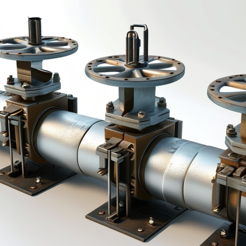
Before choosing supports, define what the cold piping system must do. Is it transporting chilled water, refrigerated fluid, or another low-temperature medium? The answer affects insulation, support spacing, load capacity, and material selection. A line operating below ambient temperature can collect condensation quickly. Moisture may damage nearby steelwork and weaken insulation joints.
Record the operating and design temperatures, pipe diameter, fluid weight, pressure, and expected movement. Thermal contraction can pull against rigid supports when temperatures fall. Sliding supports, guides, and anchors must control movement without crushing the insulation. Support surfaces should spread the load and prevent cold bridges. In practice, a poorly insulated support can appear minor, yet create a wet patch within hours.
Site conditions also matter. Check vibration, wind exposure, maintenance access, drainage, and nearby heat sources. A support suitable indoors may fail on a roof exposed to rain and sunlight. Field inspections often reveal uneven floors, crowded services, or missing clearance that drawings do not show. That is where the design needs revision. Do not assume standard spacing is always safe. Heavy valves, flanges, and instruments may require separate support points. Flexible connections also need enough room to move. A small error in alignment can transfer stress into equipment no one intended to load. Engineers should verify calculations against applicable piping and structural requirements, while installers should document actual conditions before final adjustment.
Choosing supports for cold piping requires more than checking the pipe’s weight. Load control and thermal protection must work together. Pipe shoes transfer weight to structural steel, while guides control sideways movement during contraction. Anchors restrain movement but can create high stress if placed without a flexibility review. Spring supports may help when vertical loads change during operation, but they require accurate calculations and adjustment.
Thermal protection is equally important. A support that crushes insulation can create a cold bridge, causing condensation, corrosion, or unwanted heat gain. Insulated pipe shoes with high-density inserts usually protect the insulation better than ordinary clamps. Low-friction slide plates can reduce movement resistance, yet they may increase local wear. Rigid supports are not always safer. Field conditions, vibration, and drainage details can change the best choice. That part is often underestimated.
Tips: Confirm operating and test loads before selecting support spacing. Check the insulation thickness, vapor barrier, and support insert strength together. Leave enough clearance for contraction. Inspect clamps after installation, especially where insulation looks compressed. A small gap may allow moisture inside. Also review support locations against valves, flanges, and maintenance access. I have seen designs that controlled pipe movement well but made valve removal nearly impossible. Good support design protects the pipe, insulation, and people working around it.
How to Choose the Best Supports for Cold Piping Systems?
Selecting supports for cold piping requires more than checking load capacity. The support must protect insulation from compression, gaps, and water damage. During practical inspections, I check whether the insulation stays fully supported at every hanger. A crushed section may look minor. It is not.
Choose insulation with suitable thermal resistance and enough strength for the pipe weight. High-density inserts can reduce compression around support points. For colder lines, the vapor barrier must remain continuous across joints, seams, and penetrations. Seal longitudinal joints carefully. Pay attention to supports. Any exposed metal can create a thermal bridge and attract condensation. Small openings may allow humid air beneath the insulation.
Moisture prevention also depends on valves, flanges, and support transitions. These areas often fail because they are difficult to seal neatly. Use compatible sealants and follow approved project specifications, installation instructions, and applicable codes. In field reviews, I have seen excellent insulation weakened by one unsealed penetration. That assumption failed. Inspectors should check for damp surfaces, staining, soft insulation, and dripping near supports. Leave enough access for future inspection. Photograph sealed joints before closing ceilings or covers. Good records improve reliability, although they cannot replace physical checks.
| Support or Design Element | Primary Function | Suitable Insulation Approach | Vapor Barrier Requirement | Moisture-Prevention Measures | Typical Application Range | Selection Considerations |
|---|---|---|---|---|---|---|
| Load-Bearing Insulated Pipe Insert | Transfers pipe weight to the support while maintaining insulation continuity at the support point. | High-density, low-absorption insulation insert matched to the surrounding insulation thickness. | Continuous vapor-retarder facing or sealed outer jacket across the insert and adjacent insulation. | Seal all longitudinal and circumferential joints with compatible vapor-barrier adhesive or tape. | Common for chilled-water, refrigeration, and other below-ambient piping. | Verify compressive strength, pipe diameter, support spacing, and compatibility with the insulation system. |
| Pipe Shield with Insulation Insert | Distributes clamp or hanger loads and reduces crushing of the insulation. | Use a rigid insert or load-bearing section beneath the shield; avoid placing a soft insulation layer directly under concentrated loads. | The vapor retarder must remain continuous around the shield and insert assembly. | Prevent water paths at shield edges with sealed jacketing and properly detailed end caps. | Useful for suspended horizontal piping and trapeze-supported systems. | Check shield width, load distribution, clamp pressure, and movement caused by thermal contraction. |
| Elastomeric Closed-Cell Insulation | Provides thermal insulation and resistance to water-vapor diffusion in compact assemblies. | Closed-cell flexible insulation installed tightly around the pipe; thickness is selected from the design heat-gain and condensation-control requirements. | Factory skin or facing is not automatically a complete vapor seal; seal seams, joints, and penetrations. | Keep the surface dry, protect against ultraviolet exposure where applicable, and repair cuts before commissioning. | Often used for chilled water, air-conditioning, and refrigeration lines. | Confirm temperature limits, fire performance, UV resistance, and dimensional stability. |
| Cellular Glass Insulation | Provides rigid, moisture-resistant thermal insulation with high compressive strength. | Rigid cellular glass sections can be used near supports when the system is designed for the expected loads. | Seal joints and fittings with a compatible vapor-retarder coating, sealant, or jacket system. | Use sealed joints, weatherproof jacketing in exposed areas, and compatible coatings at terminations. | Suitable for low-temperature piping and locations requiring low water absorption and strong load resistance. | Account for brittleness, joint detailing, thermal movement, and protection from mechanical impact. |
| Rigid Polyurethane or Polyisocyanurate Sections | Provides low thermal conductivity with relatively high compressive performance when properly supported. | Use prefabricated or field-fitted sections with load-bearing inserts at support locations. | Install a continuous vapor-retarder jacket; carefully seal joints, ends, and penetrations. | Protect exposed insulation with a durable, weather-resistant jacket and prevent water ingress at seams. | Used in many chilled and low-temperature piping assemblies where space efficiency is important. | Check long-term compressive strength, dimensional stability, fire classification, and service temperature. |
| Mineral Wool with Separate Vapor Retarder | Provides thermal insulation and fire resistance, but requires a dedicated moisture-control layer for cold service. | Use rigid or high-density sections at supports and avoid compressing the insulation below its design thickness. | A continuous, well-sealed vapor retarder is essential because mineral wool is not inherently a vapor barrier. | Use sealed jacketing, sealed penetrations, and protected terminations; replace insulation that becomes wet. | Appropriate where fire performance is important and a detailed vapor-control system can be installed. | Do not rely on the insulation alone to prevent condensation; verify water-vapor permeance and jacket integrity. |
| Thermal Break at Metal Supports | Reduces conductive heat flow through metal hangers, clamps, and structural attachments. | Use a load-bearing thermal-break material that can withstand the support reaction without excessive compression. | Extend and seal the vapor retarder over the thermal break and connect it to the adjacent insulation. | Eliminate unsealed gaps and prevent direct contact between cold metal surfaces and humid air. | Important at every support where a conductive metal path could create a cold spot. | Evaluate compressive strength, creep, temperature range, fire properties, and compatibility with coatings. |
| Pipe Shoes or Saddles | Provide a stable bearing surface and distribute loads on larger or heavier pipe systems. | Use a designed insulation insert or saddle assembly rather than allowing the insulation to carry concentrated loads. | Detail the vapor retarder continuously around the shoe, saddle, and adjacent insulation. | Seal shoe ends, jacket overlaps, and drainage-sensitive areas; avoid pockets where water can collect. | Common on larger-diameter, heavy, or guided piping systems. | Check vertical and lateral loads, guide forces, pipe movement, corrosion protection, and access for inspection. |
| Vapor-Barrier Jacket and Sealed Fittings | Stops humid air from reaching cold surfaces and reduces condensation risk. | Use a jacket compatible with the insulation material and service environment. | Target a continuous, low-permeance layer with sealed seams, butt joints, valves, flanges, and terminations. | Use compatible sealants and tapes; inspect for punctures, open seams, and unsealed penetrations. | Required for most below-ambient piping located in humid indoor or outdoor environments. | Vapor-barrier continuity is generally more important than jacket appearance; field joints require special attention. |
| Condensation Inspection and Maintenance | Identifies failures before moisture damages insulation, supports, ceilings, or nearby equipment. | Inspect insulation thickness, compression, gaps, damage, and wet spots at supports and fittings. | Check that the vapor retarder remains sealed after testing, maintenance, and valve operation. | Repair damaged jacketing promptly and investigate recurring condensation rather than simply adding surface coating. | Recommended during commissioning and periodic operation of all cold piping systems. | Review surface temperature, ambient dew point, system operating temperature, and areas with repeated moisture. |
Selection should be confirmed against the project design temperature, ambient dew point, insulation thickness, pipe weight, support spacing, thermal movement, fire requirements, and applicable local codes. For cold systems, a continuous and well-sealed vapor retarder is essential because small gaps can allow humid air to reach the cold pipe and cause condensation.
How to Choose the Best Supports for Cold Piping Systems?
Select Materials for Strength, Compatibility, and Corrosion Resistance
Cold piping supports must carry weight without crushing insulation or creating thermal bridges. Material selection matters more than appearance. Stainless steel, coated carbon steel, and engineered polymers can perform well, but only when their temperatures and loads match the design. ASHRAE’s Handbook—Refrigeration stresses continuous insulation and vapor protection around cold systems. A small gap can invite condensation. Moisture eventually reaches the support.
Compatibility deserves equal attention. Dissimilar metals may accelerate galvanic corrosion when water is present. Use isolating pads, sleeves, or compatible coatings between the pipe and support. Check compressive strength at the lowest operating temperature. Some polymers become brittle, while ordinary coatings may crack after repeated thermal cycling. That detail is easy to miss.
Corrosion is not a minor maintenance issue. The NACE IMPACT study estimated global corrosion costs at 2.5 trillion U.S. dollars annually, about 3.4% of global GDP. Proper support materials can reduce exposure, but they cannot replace drainage, inspection, or sound installation. Field reviews should examine wet insulation, rust staining, loosened fasteners, and flattened saddles. A stainless clamp is not automatically the best choice. It may still transfer heat or damage the vapor barrier. I would also question generic load tables; real pipe spacing, vibration, and ice buildup can produce different results. Select strength, compatibility, and corrosion resistance together. Each one matters.
Representative room-temperature properties for selecting support materials based on strength, thermal compatibility, and corrosion resistance.
Material comparison: ASTM A36 carbon steel provides high structural strength but normally requires a protective coating in corrosive or humid environments. 304 stainless steel offers strong corrosion resistance and lower thermal conductivity, helping reduce heat transfer from refrigerated piping. 6061-T6 aluminum is lightweight and has high thermal conductivity, so thermal breaks and insulation details are especially important.
Engineering note: Values shown are representative room-temperature values: minimum specified yield strength for common product forms and typical thermal conductivity near 20°C. Final selection should also consider pipe weight, operating temperature, insulation loads, galvanic compatibility, fire requirements, and applicable piping-support standards.
Choosing supports for cold piping starts with spacing, but spacing alone is not enough. MSS SP-69-2023 provides support selection guidance, while ASME B31.1 includes span recommendations for common piping materials. These values are starting points, not promises. A water-filled pipe, valve, and insulation jacket can create heavier loads than expected. Check the actual operating weight, pipe size, temperature, and vibration before fixing support locations.
Installation quality controls long-term performance. Supports should carry the pipe without crushing insulation or creating thermal bridges. Use load-bearing inserts at every insulated support point. Keep vapor barriers continuous around collars, seams, and penetrations. ASHRAE Handbook—HVAC Systems and Equipment identifies vapor control as essential for preventing condensation on cold surfaces. A small opening can become a wet, hidden failure. It may look harmless during commissioning.
Tips: Mark support centers on the insulation layout before installation. Keep supports level and aligned. Inspect the first three installations closely. Measure deflection after filling the system. Recheck supports after seasonal temperature changes. ASHRAE 90.1-2022 insulation tables can help verify minimum insulation requirements, but project humidity and surface temperature may demand more. A neat pipe rack can still perform poorly. That is worth questioning.
Record the fluid, operating temperature, pipe diameter, pressure, weight, and expected movement. Cold lines contract. The support design must control movement without crushing insulation.
Cold surfaces can collect condensation quickly. Continuous insulation and vapor protection reduce wet patches, corrosion, and heat transfer. A tiny gap may become a hidden failure.
Use sliding supports, guides, and anchors where movement requires control. Rigid supports may pull against the pipe as temperatures fall. Allow flexible connections enough room to move.
Stainless steel, coated carbon steel, and engineered polymers may work when their loads and temperatures match. Check low-temperature strength carefully. Some polymers become brittle.
Different metals may accelerate galvanic corrosion when moisture is present. Use isolating pads, sleeves, or compatible coatings. Keep water away whenever possible.
No. Spacing values are only starting points. Include pipe weight, fluid weight, insulation, valves, vibration, and possible ice buildup. Heavy valves may need separate supports.
Keep supports level, aligned, and properly centered. Use load-bearing inserts at insulated support points. Protect collars, seams, and penetrations from vapor leaks.
Inspect the first three installations closely. Measure pipe deflection after filling the system. Recheck supports after seasonal temperature changes. Look for rust stains, wet insulation, loose fasteners, and flattened saddles.
Check vibration, wind, drainage, maintenance access, heat sources, and nearby services. Roof supports face rain and sunlight. Drawings may miss uneven floors or crowded spaces.
A neat pipe rack does not guarantee good performance. Generic load tables may miss real alignment, vibration, or moisture conditions. Field evidence should revise the design when needed.
Choosing the right supports is essential for maintaining the safety, efficiency, and service life of a cold piping system. To understand how to choose supports for cold piping systems, begin by defining the operating temperature, pipe size, fluid weight, movement requirements, and environmental conditions. Support types should then be compared based on their ability to control loads, limit vibration, accommodate thermal contraction, and protect the piping from heat transfer. Special attention should be given to insulation and vapor barriers, since damaged or incomplete protection can lead to condensation, moisture intrusion, and corrosion.
Material selection is also important. Supports should provide sufficient strength while remaining compatible with the pipe, insulation, and surrounding environment. Corrosion resistance should be evaluated, especially in areas exposed to humidity or chemicals. Finally, confirm support spacing according to the system’s design requirements and inspect installation quality, alignment, contact surfaces, and insulation continuity. Proper planning, installation, and regular inspection help prevent excessive stress, moisture-related damage, and premature failures, ensuring reliable long-term performance.

Ampy Pipe